Getting Hands on LoRa with Microcontrollers
How LoRa Works with Microcontrollers
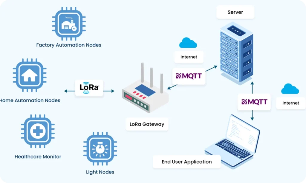
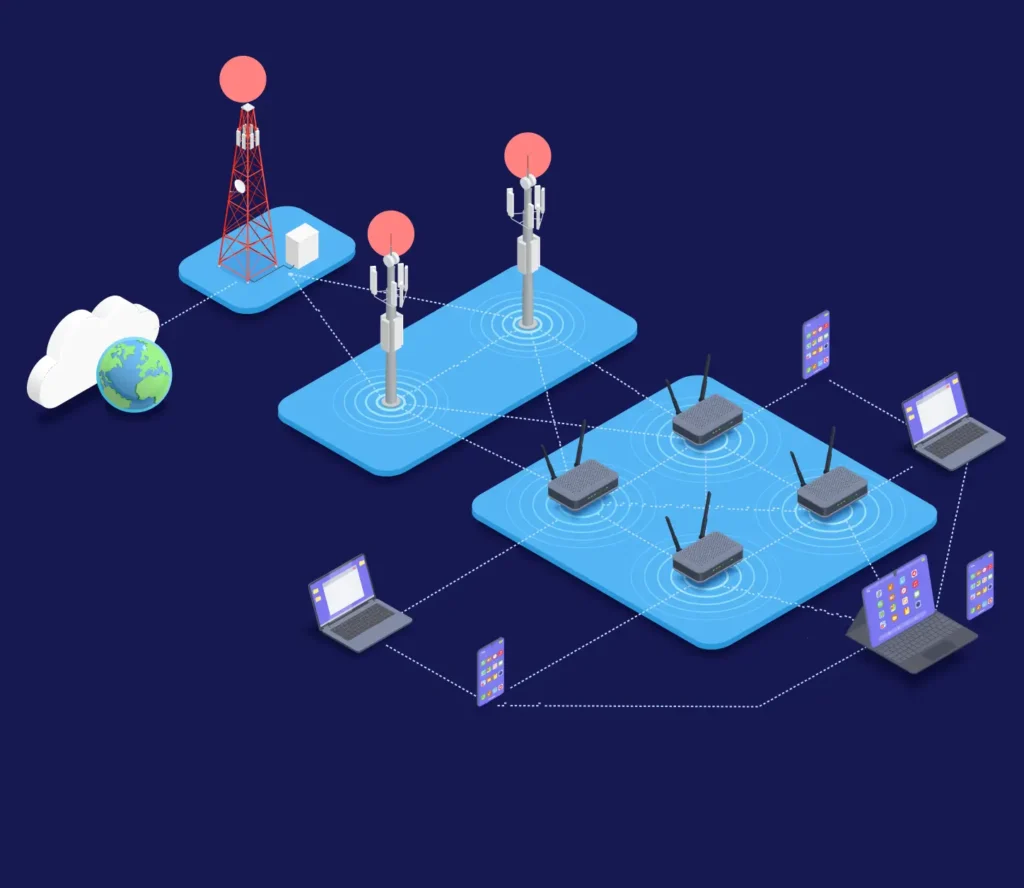
LoRa (Long Range) technology uses Chirp Spread Spectrum modulation for long-range, low-power wireless communication. It trades data rate for sensitivity and range, making it suitable for IoT devices sending small, infrequent data packets, typically controlled via SPI or UART protocols from microcontrollers.
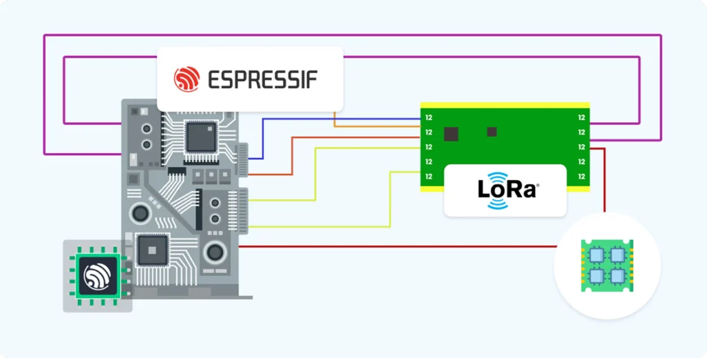
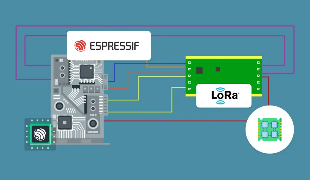
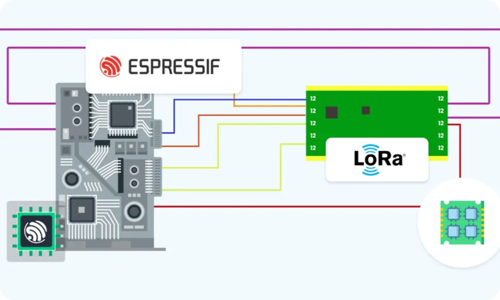
Interfacing LoRa Modules with ESP32:
Hardware and Wiring
LoRa Module Pin
Typical ESP32 Pin
Description
3.3V
3.3V
Power supply
GND
GND
Ground
MOSI
GPIO 23
SPI Master Out Slave In
MISO
GPIO 19
SPI Master In Slave Out
SCK
GPIO 18
SPI Clock
NSS (CS)
GPIO 5
SPI Chip Select
RESET
GPIO 14
Reset pin
DIO0
GPIO 2
Interrupt/Data line 0
- Connect antenna to module antenna pin.
- Ensure both MCU and module operate at compatible voltage (usually 3.3V).
- Multiple GND pins on module: at least one connected to ground is sufficient.
SPI Communication Protocol for LoRa Modules
Register Access Frame Formats
- To write a register, send one byte with MSB=1 + 7-bit register address, then send a data byte.
- To read a register, send one byte with MSB=0 + 7-bit register address, then send a dummy byte (0x00) to clock out register data.
Operation
First SPI Byte Description
Second Byte Description
Read Register
MSB=0 + 7-bit register address (0x00-0x7F)
Dummy byte 0x00
Write Register
MSB=1 + 7-bit register address (0x80-0xFF)
Data byte to write to register
Examples:
- Read version register (0x42): Send 0x42 0x00 → receive chip ID.
- Write 0x07 to register 0x0D: Send 0x8D 0x07.
Important Registers and Reset
- RegVersion (0x42): Returns chip version (expect 0x12).
- RegOpMode (0x01): Set operational modes (sleep, standby, transmit, receive).
- RegFifoTxBaseAddr (0x0E) and RegFifoRxBaseAddr (0x0F): FIFO pointers.
- Frequency Registers (0x06, 0x07, 0x08): Set carrier frequency (requires 24-bit value calculation).
- Use hardware RESET pin: Hold LOW ≥10 ms, then HIGH, wait ≥5 ms before SPI commands.
NOTE: It is important to reset LoRa device before even starting any spi read and write operation. Because if we’re not resetting it before use, it may have some previous unknown state which is not advisable for systems with tight power requirements or battery powered devices. Also reset will clear the previous initialized state and make all registers to default.
Technologies + Existing Products
					uint8_t SPI_ReadRegister(uint8_t reg)
{
  uint8_t reg_address = reg & 0x7F; // Clear MSB for read
  SPI_CS_LOW();
  SPI_Transfer(reg_address);
  uint8_t value = SPI_Transfer(0x00);
  SPI_CS_HIGH();
  return value;
}


void SPI_WriteRegister(uint8_t reg, uint8_t value)
{
  uint8_t reg_address = reg | 0x80; // Set MSB for write
  SPI_CS_LOW();
  SPI_Transfer(reg_address);
  SPI_Transfer(value);
  SPI_CS_HIGH();
}
LoRa Module Initialization Sequence
- Reset module using RESET pin.
- Verify communication by reading RegVersion (0x42).
- Set operational frequency (e.g., 868 MHz) by writing calculated values to registers 0x06, 0x07, 0x08.
- Set spreading factor (SF7-SF12), bandwidth (125/250/500 kHz), and coding rate (usually 4/5).
- Set sync word for network separation (e.g., 0xF3).
- Configure output power and LNA gain for optimal signal.
- Initialize FIFO base addresses for TX and RX.
- Enable interrupts on DIO0 pins for Tx Done, Rx Done events.
- Set to standby mode before transmit or receive.
Sending Data Workflow
- Place the module in transmit mode.
- Begin packet (beginPacket()).
- Write payload bytes to FIFO.
- End packet (endPacket() triggers transmission).
- Wait for Tx Done interrupt or poll status.
- Return to standby or sleep mode.
Receiving Data Workflow
- Place the module in receive mode.
- Wait for Rx Done interrupt or status poll.
- Read received payload from FIFO.
- Verify CRC and signal quality (RSSI, SNR).
- Return to receive mode to await further packets.
Additional Notes
- Frequency register values require conversion:
Register value= frequency x 219/(32 x 106) - Spreading factor, bandwidth, and coding rate must match on both ends.
- Antenna quality and power supply stability are critical for reliability.
- Use interrupts for efficient event-driven data handling.
Upcoming lecture:
We’ll start with using a simple echo back between two LoRa based end devices.
LoRa Uncovered: From Fundamentals to Real-World IoT Applications
Part 1: Understanding LoRa – Fundamentals and Core Concepts
Part 2: Key Concepts in LoRa Technology
Part 3: Getting Hands on LoRa with Microcontrollers